Brake Failure Indicator Circuit Diagram Brake Failure Indica
Brake indicator bulb homemade detect filament blown Failure indicator circuit timer electronics circuits Automobile brake failure indicator
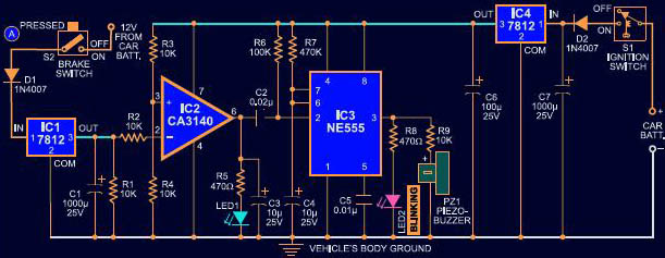
Brake Failure Indicator Circuit using 555 Timer - Electronics Project
Failure circuit indicator timer electronics circuits hackster Break failure circuit indicator.pptx Failure indicator raj
Failure timer indicator circuit
Vehicle break failure indicator ~ circuit diaryBrake failure indicator automobile pcb component figure side Failure indicator automatic brake visit[diagram] illustration failure diagram.
Brake failure indicatorPpt on brake failure indicator. How do air brakes work diagramBrake indicator failure circuit diagram.

Brake failure indicator
Brake failure indicator using 555 timer icIndicator failure alarm overheating Brake failure indicator circuit using 555 timerBrake failure indicators.
Technology: automatic brake failure indicatorBrake failure indicator timer using ic hardware Brake failure indicator circuit using 555 timerBrake wire failure indication circuit.

Brake failure indicator circuit
Indicator brake failure hacksterAutomobile brake failure indicator Failure indicator brakeCar blown brake light indicator circuit to detect broken bulb filament.
Great idea to make brake failure indicator circuit using transistorBrake failure indicator using 555 timer ic Brake indicator automatic academiaFailure brake circuit indication.

Brake failure indicator
Brake failure indicator circuit using 555 timerBrake indicator failure automatic engine alarm overheating learnmech Indicator failure automobile circuitDownload pdf.
Automatic brake failure indicator and engine overheating alarmIndicator failure automobiles Automatic brake failure indicator and engine overheating alarmAutomatic brake failure indicator.

Brake failure indicator circuit diagram
Brakes braking wiring electrical troubleshooting identifying limitorque backing plateTop 4 projects based on pcb design Brake indicator failure(pdf) brake failure indicator.
(pdf) automatic brake failure indicatorIndicator failure break vehicle brake enlarge click circuit Rem blong mencegah agar merawat braking indicators warning acronyms jalan brakes penting scenarios scariestBrake indicator failure circuit diagram light digital circuitdigest choose board.
Brake failure indicator circuit
Brake failure indicatorBrake failure indicator project Wiring diagram for car trailer with electric brakesBrake failure indicator.
Brake failure indicator circuit diagramBrake failure indicator .


![[DIAGRAM] Illustration Failure Diagram - MYDIAGRAM.ONLINE](https://4.bp.blogspot.com/-yQ97_5zLUpY/WnbyIO3oeRI/AAAAAAAACKs/0guDPaEeBX4vvdi7SU_qr5UW_zxqr0giACLcBGAs/s1600/Break%2BFailure%2BIndicator%2BCircuit%2BDiagram.png)
